
Electric Bike Wiring Diagram: Beginner’s Guide to Wiring a Hub Motor
Getting Started with Your E-Bike Kit
You just opened your new electric bike conversion kit. A bunch of colorful wires fall out everywhere. It looks like a bowl of spaghetti instead of parts for an awesome new ride. We understand how you feel. That's exactly why we made this guide. We'll help you get through the mess and give you clear, easy steps for your project. When you finish this article, you'll have more than just a working bike. You'll feel confident because you understand how your e-bike's electrical system works.
We're going to work together to:
* Find every important part in your kit.
* Learn what each wire color usually means.
* Connect everything using simple, step-by-step instructions.
* Fix the most common wiring problems with confidence.
Safety and Essential Tools
Let's talk about safety rules before we touch any wires. These steps protect you and your new parts from getting damaged. This makes your DIY project look professional.
Safety Is Non-Negotiable
We can't say this enough. Your electric bike battery holds a lot of energy. Always be careful with it. The battery must always be the very last thing you connect and the very first thing you disconnect when working on your wiring. Also, wear safety glasses every time you work. Short circuits can make sparks, and it's better to stay safe.
Your E-Bike Wiring Toolkit
The right tools make your job cleaner, faster, and more solid. You don't need a huge workshop-just a few key things.
| Tool | Why You Need It |
|---|---|
| Wire Strippers/Cutters | For making clean cuts and getting wire ends ready for connection. |
| Multimeter | The most important tool for finding wires and testing connections. |
| Zip Ties | Essential for neat, secure cable management that stops snags and damage. |
| Heat Shrink Tubing | The professional way to protect your connections from water and strain. |
| Heat Gun or Lighter | To shrink the tubing, making a sealed, strong connection. |
Understanding the Parts
An e-bike's electrical system is easier than it looks. Think of it like a human body with a heart (the battery), a brain (the controller), muscles (the motor), and a nervous system (the wires and sensors). When we understand what each part does, the electric bike wiring diagram makes sense. The power flows in a simple path: the Battery sends power to the Controller. The Controller then reads signals from your Throttle and Sensors and sends smart, controlled power to the Motor.

The Battery: The Power Source
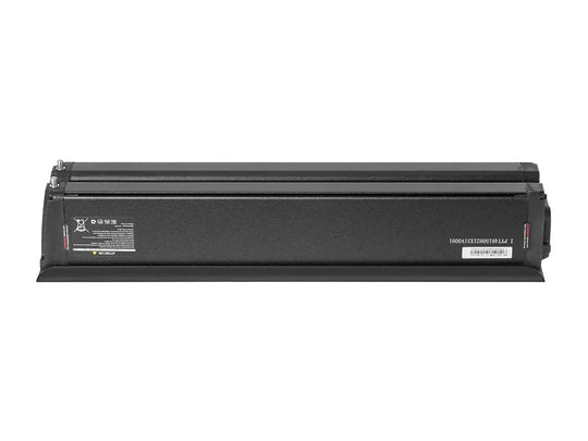
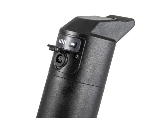
This is your e-bike's heart. It's a big rechargeable battery pack that gives Direct Current (DC) power to everything. Most modern e-bike kits use 36V, 48V, or 52V systems. Your battery and controller voltage must match. A 48V controller needs a 48V battery.
The Controller: The Brain
If the battery is the heart, the controller is the brain. This small metal box runs everything. It takes raw power from the battery, listens to your throttle or pedal-assist sensor, and then sends exactly the right amount of power to the motor. It makes the bike feel smooth and responsive instead of like an on/off switch.
The Hub Motor: The Muscle
This is what makes you move. A hub motor is a brushless DC motor inside your front or rear wheel hub. It has powerful magnets and copper windings. The most important thing to know is that it has two main wire groups: three thick phase wires and a group of five or six thin Hall sensor wires.
The Controls: How You Interact
These parts let you control your electric bike system:
* Throttle: A twist-grip or thumb lever that tells the controller you want power now.
* Pedal Assist Sensor (PAS): This sensor has a ring of magnets on your crank and a pickup on the frame that tells the controller when you're pedaling.
* Brake Levers: Many e-bike brake levers have a cutoff switch that instantly stops motor power when you pull the lever.
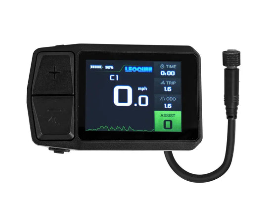
* Display: The screen on your handlebars that shows speed, battery life, assist level, and other information.
Understanding Wire Colors
This is where most DIY builders get confused. You look at wires from your controller and motor, and the colors don't match. Don't worry. While there isn't one universal standard, there are common rules that work for 90% of kits. This section helps you understand e-bike wires.
Breaking the Color Code
Use this table as your main guide. Always start by thinking your kit follows this pattern. We'll cover what to do when it doesn't in the next section.
| Function | Primary Color(s) | Secondary/Alternative Colors | What it Does |
|---|---|---|---|
| Battery Power | Thick Red (+) & Black (-) | Blue (-) is sometimes used instead of Black. | Main power lines from the battery to the controller. Always thick gauge. |
| Motor Phase | Thick Yellow, Green, Blue | No common alternatives. The thickness tells you what they are. | The three thick wires that carry high current to power the motor's windings. |
| Hall Sensors | Thin Red, Black, Yellow, Green, Blue | White, Brown, Orange. | Five or six thin wires that tell the controller the motor's position. Red is +5V, Black is Ground. |
| Throttle | Red, Black, White or Green | Red, Black, Blue. | Three-wire plug. Red is +5V, Black is Ground, and the third color is the signal wire. |
| PAS Sensor | Changes a lot. | Often Red, Black, and a signal color like Yellow or Blue. | Gives the pedal-sensing signal to the controller. |
| Brake Cutoffs | Changes. Often two identical 2-wire plugs. | Usually Black and a signal color like Yellow or White. | Two-wire connection that tells the controller to cut power. |
When Colors Don't Match
You opened your kit, and the motor Hall sensor wires are orange, purple, and grey. This happens a lot, especially when mixing parts from different brands. The solution is to identify wires by what they do, not by color, using a multimeter. Here's our process for solving this problem:
- Find the Motor Phase wires first. This is easy because they're the three thickest wires from the motor. Set them aside.
- Find the Hall Sensor bundle. This is the other group of wires from the motor, usually five thin wires in one plug.
- Find the Hall Power and Ground from the CONTROLLER. Set your multimeter to DC Volts (the 20V setting works great). Turn the controller on (without the motor connected). Test the pins on the controller's Hall sensor plug. Find the two pins that show about 5V. The positive lead of your multimeter is on the +5V wire (usually Red), and the negative lead is on the Ground wire (usually Black).
- Connect Power, Ground, and try the rest. Connect the +5V and Ground Hall wires from the controller to what you think are the matching wires on the motor (often Red and Black). The other three Hall signal wires can be connected in any order. If the motor shakes or runs badly, disconnect the battery and swap two of the signal wires. Keep trying until the motor runs smoothly.
Connecting Your Hub Motor
Now we know our parts and wires, so it's time to build. We'll follow a smart order that keeps things safe and makes the process easy. This is the main part of your electric bike wiring diagram.
Step 1: Plan Your Wire Routing
Before connecting anything, lay your parts out. Put the controller where you plan to mount it (like in a frame bag or on a rack). Run the motor cable and other wires to the controller. Make sure no wires are stretched tight or will get pinched by moving parts like suspension or steering. A little planning now saves big problems later.
Step 2: Find the Battery Connection
Find the two thickest wires on your controller, almost always heavy Red and Black. These connect to the battery. Make sure they match the main power connector from your battery. Don't connect them yet. This is the last step.
Step 3: Connect the Hub Motor to the Controller
This needs two separate connections: the big phase wires and the smaller Hall sensor plug.
Connecting the Phase Wires
Take the three thick phase wires (usually Yellow, Green, and Blue) from the motor and connect them to the matching three thick wires from the controller. Most kits use bullet connectors that push together firmly.
Pro Tip: If your motor runs backward after everything is connected, the fix is easy: just swap any two of these three phase wires. This will reverse the motor's direction.
Connecting the Hall Sensor Wires
Find the 5-pin or 6-pin Hall sensor plug from the motor and connect it to the matching plug on the controller. These plugs usually have a small arrow or tab so they can only go in one way. This connection is very important because the Hall sensors constantly tell the controller exactly where the motor is. This feedback makes the motor start smoothly and run efficiently.
Step 4: Connect the Throttle and Other Parts
Now connect your controls. The controller will have several smaller plugs for the throttle, brake lever cutoffs, PAS sensor, and display. These are often unique connectors with different numbers of pins (like the throttle has 3 pins, brakes have 2 pins), so it's hard to mix them up. Match each part to its matching plug on the controller harness.
Testing and Fixing Problems
You've done the hard work. The wiring is done, and everything looks right. Now for the big moment. Following a safe test process is key to success.
The First Test
- Before connecting the battery, lift the bike's drive wheel off the ground. You can use a stand or flip the bike upside down to rest on its handlebars and seat.
- Check all your connections one more time to make sure nothing is loose.
- Now, and only now, connect the battery to the controller. You might see a small, harmless spark as the parts in the controller charge up. This is normal.
- Turn on your system using a key, power button on the battery, or button on your handlebar display.
- Very gently and slowly use the throttle. The wheel should start spinning smoothly. Great job!
Fixing Your Wiring Problems
If things don't work perfectly, don't worry. Most problems are easy to fix. This is where understanding the electric bike wiring diagram really helps.
| Problem | Likely Cause & Solution |
|---|---|
| Motor shakes, vibrates, or won't run smoothly. | This usually means mismatched Hall sensor wires. Disconnect the battery. Try swapping the three Hall sensor signal wires (the ones that aren't Red or Black) until you find a smooth combination. Many modern controllers can run in "sensorless" mode if a Hall sensor breaks, though startup may be less smooth. |
| Motor runs, but backward. | The motor phase wires are in wrong order. Disconnect the battery. Swap any two of the three thick motor phase wires (like swap the Yellow and Green). This will reverse the motor's spin direction. |
| No power at all. Nothing happens. | Start with basics. Is the battery charged and turned on? Check the main battery connection to the controller. Look for a fuse on the battery case or on the controller's main power wire, and see if it's blown. Make sure any power switch is turned on. |
| Throttle doesn't work, but PAS does (or the other way around). | This points to a specific part connection. Check that the throttle (or PAS) is plugged into the right port on the controller. Look at the pins inside the connector to make sure none are bent or pushed out of place. |
For harder problems or unique part combinations, we really recommend checking out the Endless Sphere forums. It's an amazing community of experienced builders who have probably solved your exact problem before.

Final Steps: You Did It
You made it work. That tangled mess of wires is now a fully working, powerful electric bike system that you built yourself. By taking time to understand the parts, figure out the wires, and follow a smart process, you've done more than just follow instructions. You now have the basic knowledge to fix problems, upgrade parts, and even build another e-bike later.
Your last step is to clean up your work. Bundle loose wires neatly with zip ties, making sure they're away from any moving parts. Use heat shrink tubing on any spliced connections for weather protection and a professional look. Take a moment to feel proud of your work. You didn't just build an ebike-you learned a valuable new skill. Now go enjoy your ride!
Frequently Asked Questions
Q: What should I do if my motor wires are completely different colors than what's in the guide?
A: Use your multimeter to identify wires by function, not color. The three thickest wires are always the motor phases, and you can connect them in any order initially. For Hall sensors, find the +5V and ground wires first using your multimeter, then trial-and-error the remaining signal wires until the motor runs smoothly.
Q: Is it normal to see a small spark when I connect the battery?
A: Yes, a small spark when connecting the battery is completely normal. This happens because the capacitors inside the controller are charging up. However, if you see large sparks or hear loud pops, disconnect immediately and check your wiring.
Q: My e-bike works but the motor runs backward. How do I fix this?
A: This is an easy fix. Simply disconnect the battery for safety, then swap any two of the three thick motor phase wires. For example, if you have yellow, green, and blue phase wires, disconnect the yellow and green ones and swap their positions. This will reverse the motor direction.
Q: What voltage battery should I use with my controller?
A: Your battery voltage must exactly match your controller voltage. If you have a 48V controller, you need a 48V battery. Using mismatched voltages can damage your components or create safety hazards. Check the labels on both components to confirm compatibility.
Q: How do I know if my Hall sensors are working properly?
A: Working Hall sensors make the motor start smoothly and quietly. If Hall sensors are damaged or incorrectly wired, the motor will stutter, vibrate, or have difficulty starting from a stop. Most modern controllers can run without Hall sensors in "sensorless" mode, but startup will be less smooth and may require a small push to get going.




Leave a comment